Week 11: Input Devices
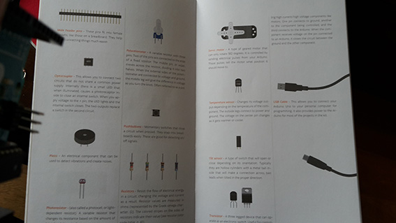
Wednesday 13/04/16 On Wednesday Neil went through the different kinds of sensors available and I must say that this was one of the subjects that I was really looking forward to getting into. Sensors are a little bit like magic to me (I guess magicians must be using some too!) Although he was quite elaborate in his descriptions and they are listed in the archives, I feel that I need to put the pictures of some here for personal reference and future use. It is always easier for me to look at images rather than text.
2d Accellerometer
3d Accellerometer
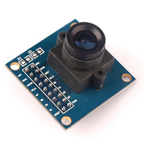
Camera
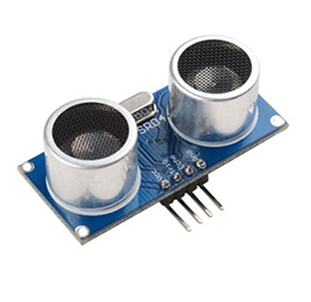
Distance Sonar Sensor
Light Phototransistor
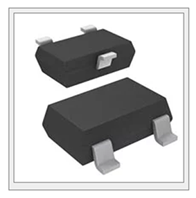
Magnetic Field
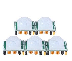
Motion Sensor
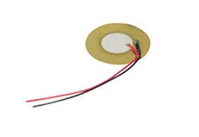
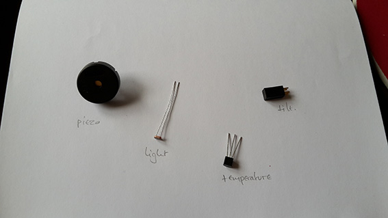
Piezzo
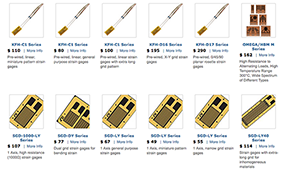
Strain Group
Temperature NTC
Temperature RTD
Thursday 13/04/16 Emma gave quite a good lecture once again regarding the sensors and went into a lot more detail. By then I really did not know which one to choose to work with because all options were open and the possibilities were endless! I thought that I could start thinking more seriously about my final project. In that case I wanted to dismantle my old insence burner and start over with it. The great goal of that product is to be able to get rid of the small platform on which the insence burner is standing and to make it more compact in general.
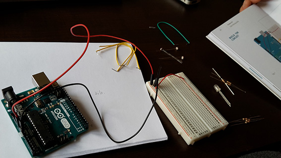
Friday 13/04/16: The plan was to get through as many Arduino tutorials as possible in order to familiarise myself with the IDE and I did complete about four of them. I find the accompanying book very useful and easy to understand.
Saturday 13/04/16: I bought a multi-meter of my own and I tested all the connections of the Fabkit which I had milled and stuffed in the previous weeks. I believe I am now fluent in understanding the routes and how to test the connections. I believe I may even be developing a system when in comes to debugging a new board!
- Have a good look that everything appears ok to the naked eye
- Make sure that all components have been soldered correctly and are making a good connection to the trace
- Make sure that no components which have orientation have been soldered in the wrong direction
- Make sure that no components which have orientation have been placed in the wrong direction in the schematic or board
- Try to eliminate all hardware issues before proceeding to software
- Begin with the software inspection. Make sure that all settings were correct and that the pins that I describe in my code are the ones through which the connections are made.
I am sure this list may change and definitely improve as I continue my quest in conquering electronics.
On Sunday 13/04/16, the plan was to make a decision on which sensor to use and what kind of board to make. My colleague Jacopo pointed out two more great websites other than Instructables, which could be an inspiration and a lead as to what I could choose to make. They were SparkFun and MakeZine. At they beginning I was toying with the idea of a sonar sensor that would be picking up sounds to provide movement to a small wooden car (This was for a performance that I am designing the props for). I then thought of the strain sensors which could pave the way towards the politically incorrect chairs I am thinking of designing and making as an alternative final project.
In the end I decided to expand on my little knowledge of infrared sensors, dismantle the incense burner which was already operating with one and work towards making it more compact. I thought that this could be very useful to me during both Input and Output weeks. I am surprised to admit that what I had proposed as a final project, now seems much simpler to do and I hope that it could be completed within the actual Fab Academy classes!
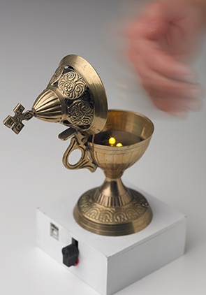
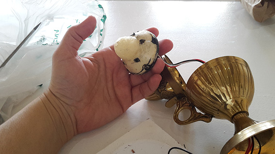
On Monday 13/04/16 I broke apart the incence burner to get access to the infrared sensor. I seem to be a little infatuated with proximity sensors because again they work like magic! It's always fun to notice their funtion on my camera and my phone! I wanted to see if I personally could use such a sensor in a more compact way.
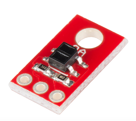
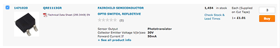
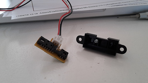
I quickly realized that I could not use the sensor on the insence burner because it already had a pcb board on it and the whole idea of the project was to design, mill and operate one ourselves. I did some research on the internet and found it’s datasheet online to see if I could re-produce the pcb, but I decided to search for a much smaller sensor and board which I found here.
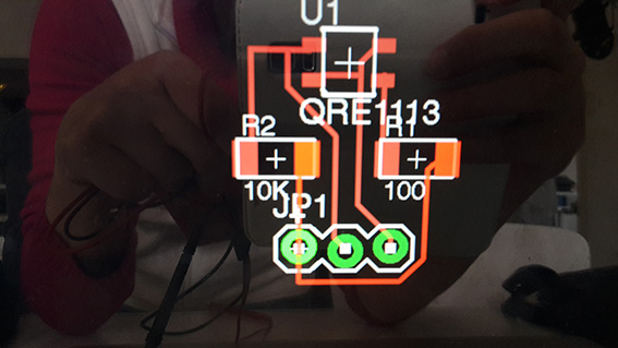
I downloaded the schematic and started re-producing it. I quickly stumbled on a problem which was that the specific sensor could not be found in the Eagle libraries. Thankfully Sparkfun had the solution, so I added the Sparkfun component libraries to Eagle and I was set! I finished the schematic and from there I drew the board view.
Because my board was pretty simple in it’s routing I decided to give the Autoroute command a shot. I followed this tutorial which was sent to us by Emma in the previous weeks and it worked fine. I was ready to mill on Tuesday morning according to my appointment. The only issue I had, was making the border of the pcb because for some reason I just could not follow Emma's simple tutorial which I had successfully done before! At some point I thought it was the fact that I had the grid off, then I thought it was because I had not made the drawing area smaller and in general I was having a very hard time in Eagle because it had been a very long time since we last used it. I do wish I was more fluent with it and I hope I will find some time to invest in getting to know it.
I also burned the bootloader on my Fabkit following this excellent tutorial by Luis Carvao and a lot of active support by my colleague Jacopo! Of course we had wasted a LOT of time trying to burn the booloader through the FTDI cable until we realised that we had to use the ISP to do it! We checked online for the ISP pinout and then connected the respective headers to the respective pins. That was when it worked! In order for it to complete the bootloader installation, the button of the Fabkit needed to be pressed and the reset pin need not be connected.
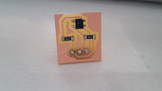
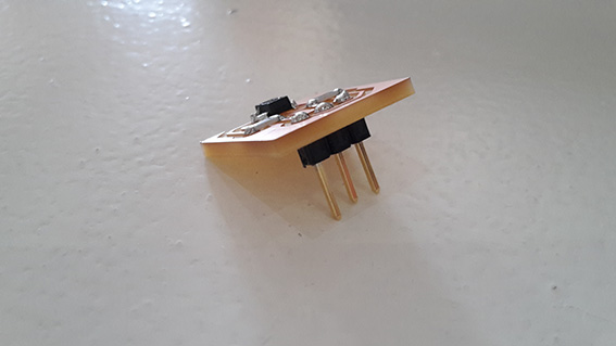
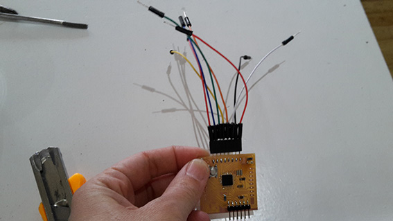
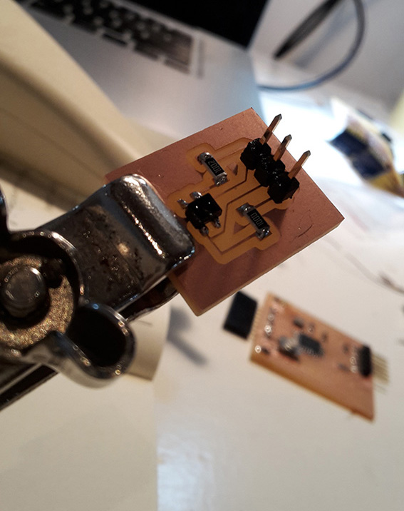
Tuesday 13/04/16: Early morning I went to mill my boards. At first I thought that maybe I had designed the pads for it wrongly or that I had added a different component on the board because the pads on which the sensor was supposed to be fixed seemed very small. When the order arrived I quickly realized that the sensors were indeed very, very small.
I milled quite easily and have gladly realized how fluent I have become with the Modela! I stuffed the board quite easily and I double checked the traces and connections with the multi-meter
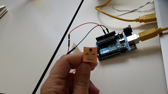
All my hardware was completed and I proceeded to program my sensor board through the FabKit. This of course was not a very easy task for a beginner at programming so I decided to first proceed with the Arduino and then with the FabKit - only if I had the time to…
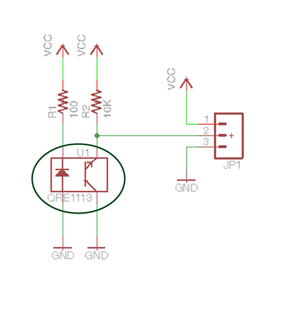
I followed the tutorial on the sparkfun page here but the IDE kept producing the message that there was something wrong with the connections. In the end Emma realized that the infrared sensor had an LED attached to it which of course has an anode and a cathode. I had placed the LED in the wrong direction (on the actual schematic) with the cathode to VCC and that was why I was not getting any correct readings.
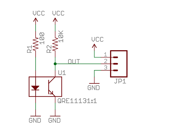
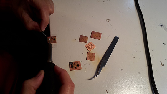
I had to re-design and mill again. By that time it was almost closing time for the FabLab but I did re-draw it and went to mill… only to realize that there was something wrong with my connections! The VCC pad was connected to nothing!
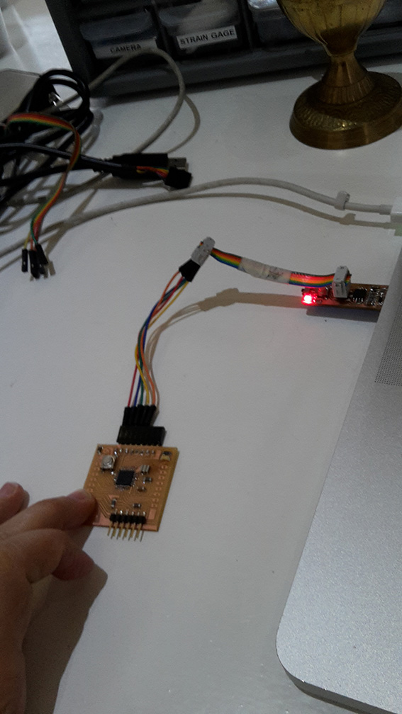
With the help of Emma (who is really, really fluent on Eagle) we drew a new board and I milled. This time one of the traces got worn out, during the next attempt a pad got detached and I decided that I should mill a few just in case this keeps happening! I think I milled more than 7 boards today and I did manage to finalize one of them and get serial readings from it.
I am totally pleased that I have tried a new board and that I have discovered new territories in making my insence burner more compact. However, most valuable to me was the fact that I finally clarified in my head once and for all the *simple* facts that:
- A Fab ISP is used to program other boards (as well as the Fab Kit)
- The Echo hello board is one of the many boards that one can make and it did consist of an input (switch) and an output device
- The Fab kit is a more capable and even sophisticated board that can be used to program other boards which are fitted with either simple or complicated input/output devices
- An Arduino IDE and boards are ready made electronic boards designed for dummies (like me) and they can do all of the above! (I could be using only Arduino from now on, but I just loved the Modela too much to give it up!)
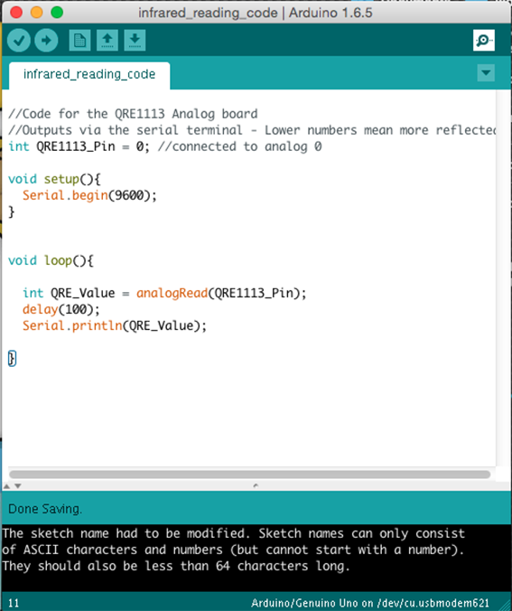
In the image above, there is the code as I had first implemented it. As one can see, I had not declared the pinMode in my code as an INPUT pin and therefore I was getting some readings, but such that were making no sense at all. The numbers were not changing in any way that was making sense so I had to declare the pinMode as shown in the image below.
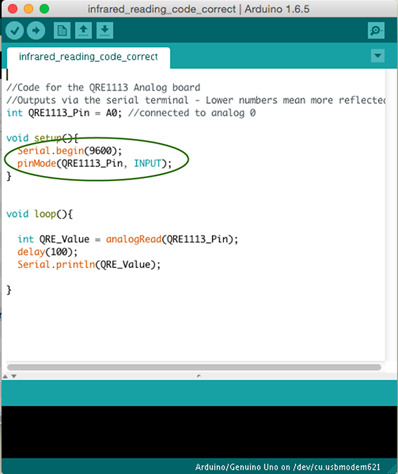
Finally I was able to get the results I needed and the sensor was responding to the light - as seen in the video below. From this simple error in code, I am finally able to understand that 'int' is the declaration of the pin from where the reading should me taken (in this case (A0)). QRE1113 is the type of my sensor. In 'void setup', 'Serial.begin' sets the baud rate at which the reading should begin and 'pinMode' is the declaration of the A0 pin as an INPUT pin. In 'void loop' I am asking the IDE to take an analogue reading from the same pin and I set the delay between the reading to 100. With 'Serial.println', I am telling it to show me those readings in the 'Serial Monitor'. Pretty basic? Only now I am getting it! The date today is 23/05/16!
Eagle Schematic— File Eagle Board— File Path— File Cut— File Serial Reading Code— File Input Devices Lecture Amsterdam Machine Review Back to Weekly Assignments Home